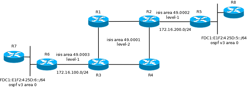
To learn about and test the capabilities of site to site tunneling I built the following network, which consists of an IPv4 core (the Internet / legacy corporate network) and two IPv6 islands. The goal here is to enable communications between the two IPv6 endpoints R7 and R8.
As an additional challenge, I built the core IPv4 network using ISIS as the routing protocol. I had never used ISIS before and with ISIS being the basis for TRILL, I thought that some first hand experience with it might come in handy. The ISIS configuration is based on a most excelent tutorial I stumbled across while doing research on FCoE and data center bridging (http://http://www.menog.net/menog-meetings/menog4/presentations/MENOG4-ISIS-Tutorial.pdf). I won’t go into the details here, so for the purposes of this entry the IPv4 network can just be considered a cloud.
In this first attempt I decided to try my hand at using an automatic 6to4 tunnel as described in: http://www.cisco.com/en/US/docs/ios/ipv6/configuration/guide/ip6-tunnel_ps6441_TSD_Products_Configuration_Guide_Chapter.html. The tunnel was built between R5 and R6.
One of the interesting things about automatic 6to4 tunnels is that as long as you have end to end IPv4 connectivity between the IPv4 interfaces on your tunnel endpoints, connectivity between the tunnel interfaces will work automatically due to the fact that the IPv4 address is encoded in the tunnel address (AC.10.C8.02 = 172.16.200.2). Through this mechanism, the tunnel destinations are automatically derived. If the IPv6 tunnel interfaces of the routers are the next hops in a routing table, then tunnels will be “built” on demand as traffic is routed towards the end destination. The one essential command is a static route defining that the whole 2002::/16 network is reachable across the tunnel interface:
ipv6 route 2002::/16 Tunnel0
The challenges is configuring dynamic routing between the two networks so that the remote networks are known. Most dynamic routing protocols will will not work across the tunnel interfaces. The only one that should work is BGP. For this test, however, I configured static routes on each end. For example on R5:
ipv6 route FDC1:E1F2:425D:6::/64 2002:AC10:6402::1
The opposite route was added to R6. I then redistributed this route into the local routing processes (OSPF in this case) and had connectivity between R7 and R8.
As mentioned, BGP will probably work fine if the other end of the tunnel is a service provider for the IPv6 Internet. This would be a standard model for connecting and routing with service providers. For enterprises, where both locations are internal offices (a data center and a branch office for example), BGP would not be the normal routing protocol chosen. An alternative, since both ends of the tunnel are under the same administrative control, would be to run a totally different tunneling model such as DMVPN, which would allow for OSPF to be implemented as the site-to-site routing protocol. The complete tunnel interface configurations on both ends are listed below.
For R5:
interface Tunnel0
 no ip address
 no ip redirects
 ipv6 address 2002:AC10:C802::1/64
 ipv6 ospf 100 area 0
 tunnel source Ethernet0/0
 tunnel mode ipv6ip 6to4
!
interface Ethernet0/0
 ip address 172.16.200.2 255.255.255.0
For R6:
interface Tunnel0
 no ip address
 no ip redirects
 ip ospf network non-broadcast
 ipv6 address 2002:AC10:6402::1/64
 ipv6 ospf 100 area 0
 tunnel source Ethernet0/0
 tunnel mode ipv6ip 6to4
!
interface Ethernet0/0
 ip address 172.16.100.2 255.255.255.0
The output from R8:
R8# ping ipv6 FDC1:E1F2:425D:6:CE08:13FF:FE40:0
Type escape sequence to abort.
Sending 5, 100-byte ICMP Echos to FDC1:E1F2:425D:6:CE08:13FF:FE40:0,
timeout is 2 seconds:
!!!!!
Success rate is 100 percent (5/5), round-trip min/avg/max=180/219/312ms

