Category Archives: IPv6

IPv6 Router Configs

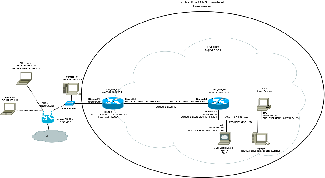
The first step in setting up the network was to configure the routers.  The LAB environment is shown in a previous post. As shown in the diagram, I used two 3640 routers with IOS 12.4(21).  Both routers were configured as IPv6 only routers and ospfv3 as the routing protocol between them.  On R2 I added a ISATAP tunnel interface to allow for access to the lab environment from a dual stack client on the external wireless LAN network.

Router R1 was configured as follows:

ipv6 unicast-routing
ipv6 cef
!
interface Ethernet0/0
 no ip address
 half-duplex
 ipv6 address FDC1:E1F2:425D:1::/64 eui-64
 ipv6 enable
 ipv6 ospf 1 area 0
!
interface Ethernet0/1
 no ip address
 half-duplex
 ipv6 address FDC1:E1F2:425D:2::/64 eui-64
 ipv6 enable
 ipv6 ospf 1 area 0
!
ipv6 router ospf 1
router-id 10.10.10.1
 log-adjacency-changes
!

R2 was configured similarly:

ipv6 unicast-routing
ipv6 cef
!
interface Tunnel0
 no ip address
 no ip redirects
 ipv6 address FDC1:E1F2:425D:3::/64 eui-64
 no ipv6 nd suppress-ra
 tunnel source Ethernet0/1
 tunnel mode ipv6ip isatap
 ipv6 ospf 1 area 0
!
interface Ethernet0/0
 no ip address
 half-duplex
 ipv6 address FDC1:E1F2:425D:1::/64 eui-64
 ipv6 enable
 ipv6 ospf 1 area 0
!
ipv6 router ospf 1
 router-id 10.10.10.2
 log-adjacency-changes
!

Looking at the routing table, you can see that all routes are present including the route for the tunnel interface.

3640_ipv6_R1#sh ipv6 route
IPv6 Routing Table - 7 entries
Codes: C - Connected, L - Local, S - Static, R - RIP, B - BGP
       U - Per-user Static route
       I1 - ISIS L1, I2 - ISIS L2, IA - ISIS interarea, IS - ISIS summary
       O - OSPF intra, OI - OSPF inter, OE1 - OSPF ext 1, OE2 - OSPF ext 2
       ON1 - OSPF NSSA ext 1, ON2 - OSPF NSSA ext 2
C   FDC1:E1F2:425D:1::/64 [0/0]
     via ::, Ethernet0/0
L   FDC1:E1F2:425D:1:CE01:15FF:FED4:0/128 [0/0]
     via ::, Ethernet0/0
C   FDC1:E1F2:425D:2::/64 [0/0]
     via ::, Ethernet0/1
L   FDC1:E1F2:425D:2:CE01:15FF:FED4:1/128 [0/0]
     via ::, Ethernet0/1
O  FDC1:E1F2:425D:3::/64 [110/11121]
     via FE80::CE00:15FF:FED4:0, Ethernet0/0
L   FE80::/10 [0/0]
     via ::, Null0
L   FF00::/8 [0/0]
     via ::, Null0

When pinging and tracing the route to the tunnel interface from the IPv6 interface on the Windows7 host, you can see that the connection works:

C:\Users\cbroccoli>ping FDC1:E1F2:425D:3:0:5EFE:C0A8:10A
Pinging fdc1:e1f2:425d:3:0:5efe:192.168.1.10 with 32 bytes of data:
Reply from fdc1:e1f2:425d:3:0:5efe:192.168.1.10: time=43ms
Reply from fdc1:e1f2:425d:3:0:5efe:192.168.1.10: time=9ms
Reply from fdc1:e1f2:425d:3:0:5efe:192.168.1.10: time=7ms
Reply from fdc1:e1f2:425d:3:0:5efe:192.168.1.10: time=10ms
Ping statistics for fdc1:e1f2:425d:3:0:5efe:192.168.1.10:
Packets: Sent = 4, Received = 4, Lost = 0 (0% loss),
Approximate round trip times in milli-seconds:
Minimum = 7ms, Maximum = 43ms, Average = 17ms
C:\Users\cbroccoli>tracert -6 FDC1:E1F2:425D:3:0:5EFE:C0A8:10A
Tracing route to fdc1:e1f2:425d:3:0:5efe:192.168.1.10 over a maximum of 30 hops
1     9 ms     3 ms     1 ms  fdc1:e1f2:425d:2:ce01:15ff:fed4:1
2    26 ms     7 ms     5 ms  fdc1:e1f2:425d:3:0:5efe:192.168.1.10
Trace complete.
IPv6 Tests

As my next experiment, I decided to build an IPv6 Lab to see if:

  1. I can get IPv6 running in an isolated environment
  2. I can get services running such as DNS and HTTP running over IPv6
  3. I can access the IPv6 services from IPv4 only hosts

After some work, mostly due to my lack of experience with installing BIND from scratch and learning how to configure Apache for IPv6, I finally got the following environment up and running:

(click on the diagram for a larger image)

As it turned out, I was also able to reach all of my goals.  For the most part, somethings were straight forward, others were not so straight forward. So that this post doesn’t get too long I will list the steps I took and the configurations I used in individual posts.

IPv6 Addressing

Before I start with the actual configuration, a word on addressing.

I understand that I should use my own unique local unicast address (ULA) as defined in RFC4193 so that my network is compliant with best practice IPv6 implementations. ULAs are not expected to be routed on the global Internet.  They are routable inside of a more limited area such as a site.  They may also be routed between a limited number of sites.   ULAs are all part of the FD::/7 (officially FC::/7 with the lowest order bit set to one) network. Based on this, 2,199,023,255,55 /48 subnets can be defined.  The hope is that if organizations pick random /48 subnets, the chances of two companies who need to communicate directly with one another (communication between a limited number of sites) picking the same subnet are extreamly low.  This solves the problem currently present in IPv4 where most companies choose one of the RFC1918 networks and the chances of a collision are very high. Therefore, for B2B connections or mergers and acquisitions, IPv6 should be much better than IPv4.

So in that vain, I googled a tool to do just that and I got the following ULA from SixXS (www.sixxs.net): fdc1:e1f2:425d::/48.   I will subnet my networks into /64 subnets which will allow me to have 65’536 subnets.

The subnets I am using then are:

  1. fdc1:e1f2:425d:1::/64 – Link between routers
  2. fdc1:e1f2:425d:2::/64 – Host subnet (VBox Host Internal Network)
  3. fdc1:e1f2:425d:3::/64 – Tunnel interface for ISATAP tunnel endpoint.

I configured all routers with a EUI-64 address for the host portion of the address, which is generated by the router automatically.  The EUI-64 address is generated as follows:

“For all IEEE 802 interface types (for example, Ethernet, and FDDI interfaces), the first three octets (24 bits) are taken from the Organizationally Unique Identifier (OUI) of the 48-bit link-layer address (the Media Access Control [MAC] address) of the interface, the fourth and fifth octets (16 bits) are a fixed hexadecimal value of FFFE, and the last three octets (24 bits) are taken from the last three octets of the MAC address. The construction of the interface ID is completed by setting the Universal/Local (U/L) bit—the seventh bit of the first octet—to a value of 0 or 1. A value of 0 indicates a locally administered identifier; a value of 1 indicates a globally unique IPv6 interface identifier.” ( see Cisco IOS IPv6 Configuration Guide, Release 12.4 for more information).