I just finished the first lab module on the Big Switch Networks SDN controller. The lab was very well structured and gave me a good feel for how it works and how it would compare to managing a similar Cisco style network. The concepts would take a little getting used to but the overall impression is that the learning curve would not be that steep. The BSN Controller uses a standard Cisco CLI like interface to show and modify the configuration. All components, spine and leaf switches, routers, tenants, etc. are contained in the same configuration file so I can see a CLI solution becoming cumbersome after a while as the file would get very large in a real datacenter. However, being able to look at specifics of the configuration via CLI is always nice and troubleshooting using debug commands is also a great benefit.
The module ended with a review of the GUI which is probably the way to go for day to day operations. Of course in a real productive system, the biggest benefits will come with orchestration and integration into either an OpenStack or VMWare solution.
Here is an excerpt from the configuration for reference based on the following topology…
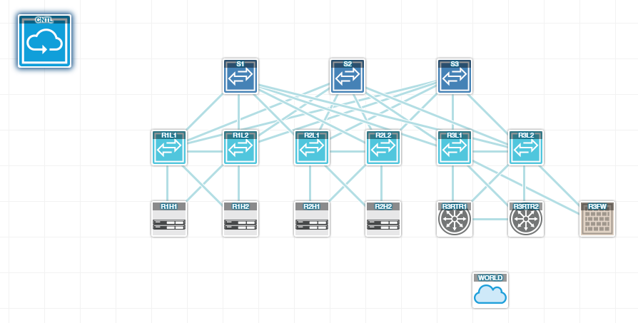
Big Switch Lab Topology
 54 login: admin
 admin@54.166.155.75's password:
 Last login: Mon Aug 3 06:39:47 2015 from 54.224.58.210
 Big Cloud Fabric Appliance 2.6.0 (bcf-2.6.0 #265)
 Logged in as admin, 2015-08-03 07:51:42.971000 UTC, auth from 54.224.58.210
 10.37.169.132> en
 10.37.169.132# sh run
 !
 ! Big Cloud Fabric Appliance 2.6.0 (bcf-2.6.0 #265)
 ! Current Time: 2015-08-03.07:51:49
 !
 version 1.0
! ntp
 ntp server 0.us.pool.ntp.org
! aaa
 aaa accounting exec default start-stop local
! local
 local node
 interface ethernet0
 service openflow
 service secure-api
 service secure-ns-api
 service secure-web
 service ssh
 service sync
 service syslog
 service web
! user
 user admin
 full-name 'Default admin'
 hashed-password method=PBKDF2WithHmacSHA1,salt=bfklbm1eiP8UB9Rx2tRbnA,
     rounds=10000,Ei1Sj4GiBNZchV707iJ1jrXb
 Ca_L26KhmoT5t22cxyg
! group
 group admin
 associate user admin
! controller
 controller
 name VirgoSupercluster
! switch
 switch R1L1
 fabric-role leaf
 leaf-group R1
 mac 00:00:00:02:00:01
switch R1L2
 fabric-role leaf
 leaf-group R1
 mac 00:00:00:02:00:02
switch R2L1
 fabric-role leaf
 leaf-group R2
 mac 00:00:00:02:00:03
switch R2L2
 fabric-role leaf
 leaf-group R2
 mac 00:00:00:02:00:04
switch R3L1
 fabric-role leaf
 leaf-group R3
 mac 00:00:00:02:00:05
switch R3L2
 fabric-role leaf
 leaf-group R3
 mac 00:00:00:02:00:06
switch S1
 fabric-role spine
 mac 00:00:00:01:00:01
switch S2
 fabric-role spine
 mac 00:00:00:01:00:02
switch S3
 fabric-role spine
 mac 00:00:00:01:00:03
! port-group
 port-group FW-01
 member switch R3L1 interface R3L1-eth5
 member switch R3L2 interface R3L2-eth5
port-group R1H1
 member switch R1L1 interface R1L1-eth5
 member switch R1L2 interface R1L2-eth5
port-group R1H2
 member switch R1L1 interface R1L1-eth6
 member switch R1L2 interface R1L2-eth6
port-group R2H1
 member switch R2L1 interface R2L1-eth5
 member switch R2L2 interface R2L2-eth5
port-group R2H2
 member switch R2L1 interface R2L1-eth6
 member switch R2L2 interface R2L2-eth6
port-group RTR-01
 member switch R3L1 interface R3L1-eth6
 member switch R3L2 interface R3L2-eth6
port-group RTR-02
 member switch R3L1 interface R3L1-eth7
 member switch R3L2 interface R3L2-eth7
! tenant
tenant External
 logical-router
 route 10.0.0.0/24 next-hop tenant system
 route 10.0.1.0/24 next-hop tenant system
 route 10.0.2.0/24 next-hop tenant system
 route 0.0.0.0/0 next-hop rtr
 interface segment Ext-01
 ip address 10.0.3.1/24
 interface segment Ext-02
 ip address 10.0.4.1/24
 interface tenant system
 next-hop-group rtr
 ip 10.0.3.2
 ip 10.0.4.2
 segment Ext-01
 member port-group RTR-01 vlan untagged
 segment Ext-02
 member port-group RTR-02 vlan untagged
tenant Green
 logical-router
 route 0.0.0.0/0 next-hop tenant system
 interface segment QA
 ip address 10.0.2.1/24
 interface tenant system
 segment QA
 member port-group R2H2 vlan untagged
tenant Red
 logical-router
 apply policy-list FireWall
 route 0.0.0.0/0 next-hop tenant system
 interface segment App
 ip address 10.0.1.1/24
 interface segment FW-01
 ip address 10.0.5.1/24
 interface segment Web
 ip address 10.0.0.1/24
 interface tenant system
 next-hop-group ServiceNode
 ip 10.0.5.2
 policy-list FireWall
 10 permit segment-interface Web any to tenant Red segment App
    next-hop ServiceNode
 11 permit any to any
 segment App
 member port-group R2H1 vlan untagged
 segment FW-01
 member port-group FW-01 vlan untagged
 segment Web
 member port-group R1H1 vlan untagged
 member port-group R1H2 vlan untagged
tenant system
 logical-router
 route 0.0.0.0/0 next-hop tenant External
 interface tenant External
 interface tenant Green
 interface tenant Red
